
Introduction
Building your first FPV drone is one of the most rewarding experiences in the RC hobby. Not only do you save money compared to buying a pre-built quad, but you also gain the knowledge needed to repair and upgrade your drone confidently. This guide walks you through every step from component selection to your first maiden flight.
Essential Components
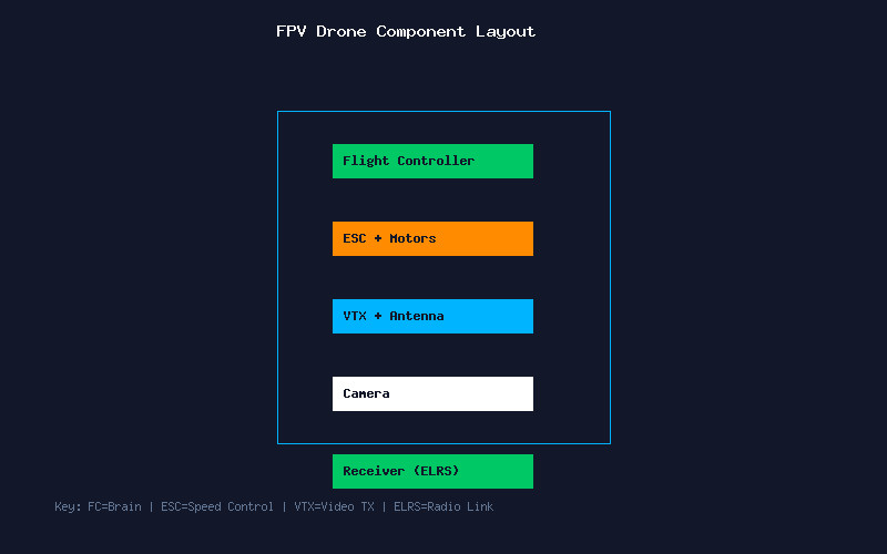
Every FPV drone consists of six core subsystems. The frame provides the structural foundation — for beginners, a 5-inch freestyle frame with replaceable arms is ideal. The flight controller (FC) is the brain of your drone, running Betaflight firmware. The electronic speed controllers (ESC) translate the FC signals into motor rotation. Motors — typically 2207 or 2306 size for 5-inch builds — provide thrust. The video transmitter (VTX) sends the camera feed to your goggles, and the receiver (RX) captures your radio commands.
For a beginner build, we recommend: a Source One V5 frame, SpeedyBee F405 V4 stack (FC+ESC combo), 2207 1950KV motors (for 6S), a Rush Tank Solo VTX, Caddx Ratel 2 camera, and an ExpressLRS receiver. Total cost: approximately $200-250 for quality components.
Tools You Absolutely Need
Quality tools make the difference between a clean build and a frustrating experience. Invest in a temperature-controlled soldering iron (TS100 or Pinecil are excellent), 60/40 rosin-core solder (0.8mm diameter), a smoke stopper for safe first power-up, a multimeter for continuity testing, hex drivers (1.5mm, 2mm, 2.5mm), and quality heat shrink tubing. A helping hands tool with a magnifying glass makes soldering small pads much easier.
Step-by-Step Assembly
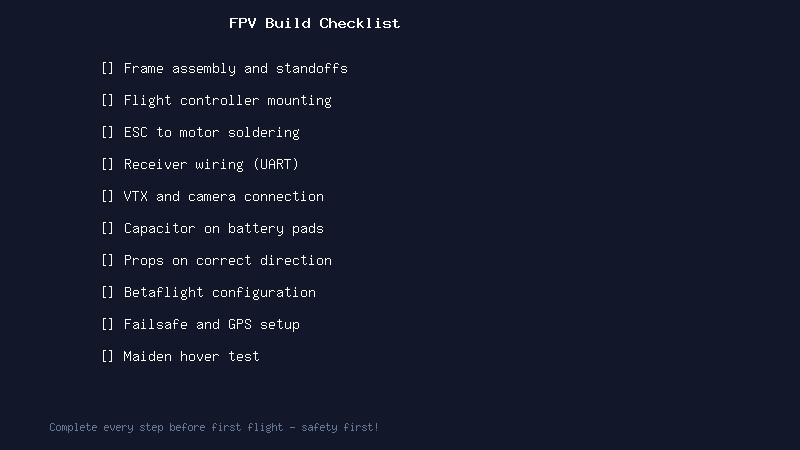
Step 1: Frame Assembly. Start by assembling the frame arms to the bottom plate. Do not fully tighten screws yet — you will need to adjust for component fitment. Install the standoffs that separate the bottom and top plates.
Step 2: Motor Mounting. Attach motors to the frame arms using M3 screws. Apply a small amount of blue Loctite to prevent loosening from vibration. Route the motor wires neatly along the arms toward the center stack.
Step 3: Stack Installation. Mount the FC and ESC using the provided nylon standoffs and rubber grommets for vibration isolation. The ESC goes on the bottom, FC on top. Connect the motor wires to the ESC pads — note the order does not matter at this stage as you can remap in Betaflight later.
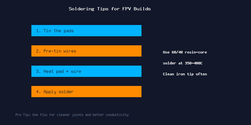
Step 4: Soldering. Tin each pad on the ESC and FC first. Pre-tin every wire. Then join them — heat the pad, introduce the wire, and let the solder flow. A good joint is shiny and smooth. Avoid cold joints (dull, grainy appearance) at all costs.
Step 5: Peripheral Wiring. Connect your receiver to a free UART (TX to RX, RX to TX, plus 5V and GND). Wire the VTX to another UART for SmartAudio control. Connect the camera video wire to the FC camera input pad. Always double-check voltage requirements — some cameras need 5V while others accept battery voltage.
Step 6: Capacitor Installation. Solder a low-ESR capacitor (35V 470uF or larger) directly to the battery pads on the ESC. This smooths voltage spikes and reduces video noise dramatically.
Betaflight Configuration
Connect your FC to Betaflight Configurator via USB. Flash the latest stable Betaflight 4.6 firmware targeting your specific FC board. Apply the default configuration, then customize:
- Ports tab: Configure UARTs for your receiver (Serial RX) and VTX (TBS SmartAudio or IRC Tramp).
- Configuration tab: Set receiver protocol to CRSF (ExpressLRS) or SBUS. Enable bidirectional DShot for ESC telemetry.
- PID Tuning tab: Start with default PIDs — they fly great on most modern builds.
- Modes tab: Set up ARM, Angle (for emergencies), and Beeper switches on your radio.
- OSD tab: Configure your on-screen display elements — at minimum include battery voltage, RSSI, link quality, and a timer.
Pre-Flight Safety Checks
Before your first flight: use a smoke stopper when plugging in the battery for the first time — this $5 device can save your entire build. Check motor direction in Betaflight (front-right and rear-left spin clockwise, front-left and rear-right spin counter-clockwise). Verify your failsafe works by turning off the radio while connected — the motors should stop. Set your VTX to a legal power level and frequency for your region. Finally, test hover at low altitude in a safe, open area.
Conclusion
Building your first FPV drone teaches you every aspect of how these machines work. When you inevitably crash (and you will), you will know exactly how to repair it. Take your time with the soldering, double-check every connection, and most importantly — enjoy the process. Your first FPV flight on a drone you built yourself is an unforgettable experience.