
Betaflight is the firmware that runs on nearly every modern FPV flight controller, and setting it up correctly is essential for a safe and enjoyable flying experience. This walkthrough takes you from a fresh firmware flash to a ready-to-fly quad, covering every tab in the Betaflight Configurator in the right order. Whether you are building your first drone or troubleshooting a problematic setup, follow this guide step by step.
1. Before You Begin — Required Tools and Preparation
Download the Betaflight Configurator from the Chrome Web Store or GitHub releases page. The standalone version is recommended — it updates independently from Chrome. You will also need a USB data cable (not charge-only), and for any ESC configuration, a LiPo battery. Ensure your flight controller is securely mounted and all solder joints are inspected before powering up. Quality flight controllers are available at UAVMODEL.
2. Firmware Flash — Starting Clean
Flashing the latest stable Betaflight firmware ensures you have all bug fixes and the latest features:
- Open the Firmware Flasher tab. Do NOT connect yet.
- Hold the boot button on your flight controller while plugging in USB. The FC enters DFU mode and Configurator shows “DFU” in the port dropdown.
- Select your target. Common targets: STM32F405 for F4-based FCs, STM32F722 for F7, STM32H743 for H7. Auto-detect usually works.
- Choose the latest stable release (not a release candidate unless you know why).
- Enable “Full chip erase” — this wipes all previous settings and prevents configuration conflicts.
- Click “Flash Firmware.” Wait for completion. The FC will reboot automatically.
3. Configuration Tab — Core Settings
After flashing, connect normally (no boot button) and go to the Configuration tab. Set these in order:
- ESC/Motor Protocol: DSHOT600. Universal, digital, no calibration needed. If your ESCs support it, DSHOT300 or 600 both work identically in practice.
- Motor direction: “Props out” (reversed) is the modern standard. It pushes debris away from the camera lens instead of flinging it onto the lens. Set it here, then use the Motor Direction wizard (Motors tab) to configure.
- Receiver: Serial-based receiver, CRSF protocol (for ELRS and Crossfire). If using FrSky or FlySky, select the appropriate serial protocol.
- Arming angle: 180 degrees (allow arming at any angle). This is important for turtle mode recovery.
- GPS: Enable if you have a GPS module. Set protocol to UBLOX. Enable “Auto Config” and “Auto Baud.”
- PID loop frequency: 8kHz (default). For F4 boards, 8kHz/8kHz is standard. F7 and H7 can run higher but it offers negligible benefit.
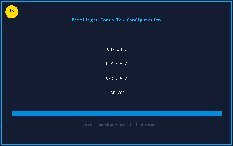
4. Ports Tab — UART Assignment
The Ports tab maps physical UARTs to functions. This is the number one place beginners make mistakes:
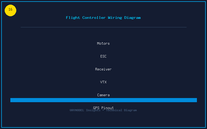
- Receiver UART: Find the UART your receiver is soldered to (check your FC wiring diagram). Enable “Serial Rx” on that UART only. Do NOT enable MSP or anything else.
- VTX control UART: If your VTX supports SmartAudio or Tramp protocol, find its UART and enable “Peripherals” → select the correct protocol (TBS SmartAudio or IRC Tramp).
- GPS UART: Enable “Sensor Input” → “GPS” at the correct baud rate (usually 115200 for modern GPS modules).
- MSP + USB VCP: Leave USB VCP (MSP) enabled at default. This is how Configurator communicates.
Critical rule: Only ONE function per column. A UART cannot simultaneously do Serial Rx and have MSP enabled. Save and reboot after each change.
5. Receiver and Modes Setup
Go to the Receiver tab. Power on your radio. You should see colored bars moving when you move your sticks. Verify:
- Channel order: Default is AETR (Aileron=Roll, Elevator=Pitch, Throttle, Rudder=Yaw). If your radio uses TAER, change it in the Receiver tab.
- Channel endpoints: Each channel should go from exactly 1000 to 2000 with 1500 at center. Use your radio’s output/endpoint menu to adjust.
- Modes tab: Assign switches. ARM on a dedicated switch (not the same as your flight mode). Set ANGLE or HORIZON mode if you want self-leveling. Set BEEPER to a switch. Add FLIP OVER AFTER CRASH (turtle mode) to a momentary switch.
6. Motors Tab — Direction and Testing
REMOVE PROPS FIRST. This cannot be stated strongly enough. Plug in a LiPo, go to the Motors tab, and:
- Use the Motor Direction wizard. It spins each motor individually and you click which direction it should run. This automatically configures the ESC direction in BLHeli.
- Verify correct motor numbering. The diagram in the Motors tab shows which motor is which position. Spin each one individually and confirm the correct motor spins.
- Spin all four motors to maximum using the master slider (props are off, right?) and listen for unusual vibrations or grinding. Rough bearings or bent motor shafts will be obvious.
7. VTX and OSD Configuration
Go to the Video Transmitter tab. If you configured SmartAudio/Tramp on the Ports tab, you will see VTX device ready. Set your band, channel, and power level. Enable “Low Power Disarm” — this drops VTX power to 25mW until you arm, preventing overheating on the bench.
In the OSD tab, arrange your on-screen elements. Essential elements: battery voltage, RSSI (or LQ for ELRS), timer, craft name, and a warning element. Enable “Warnings” overlay so the OSD alerts you to low battery or RX loss.
8. Final Checks Before Maiden Flight
Complete this checklist on the bench before heading to the field:
- Failsafe test: Arm (props off), turn off radio — motors must stop within 1 second.
- Board orientation: Tilt quad forward — the 3D model in Setup tab tilts forward. Tilt right — model rolls right.
- Motor direction: Gentle throttle up with props on (hold quad firmly). It should push air downward on all four corners.
- Video check: Clear image at expected range. No lines when throttling up (if there are lines, check capacitor and grounding).
- GPS lock (if equipped): Wait outdoors for 8+ satellites and confirm home point in OSD.
Your flight controller is now configured and ready. The first hover should be uneventful — a properly set up Betaflight quad lifts off smoothly and hovers without drama. Happy flying!