
A proper repair and building workstation is one of those things you do not appreciate until you have one. Trying to solder delicate motor wires while the frame wobbles on an uneven surface, or hunting for the right M2 screw in a pile of hardware, turns a 15-minute repair into an hour of frustration. This guide walks through designing and printing a complete FPV repair jig that holds your quad steady, organizes your tools, and makes every repair faster and more enjoyable.
Why Print Your Own Workstation?
Commercial drone repair stands cost $40-80 and are often designed for specific frame sizes. A custom 3D printed jig costs about $8 in filament, fits your exact frames, and can be modified whenever your needs change. Plus, you can integrate features no commercial product offers – like a magnetic screw tray that catches hardware before it rolls off the bench, or a dedicated motor bell press for bearing swaps.
Core Modules
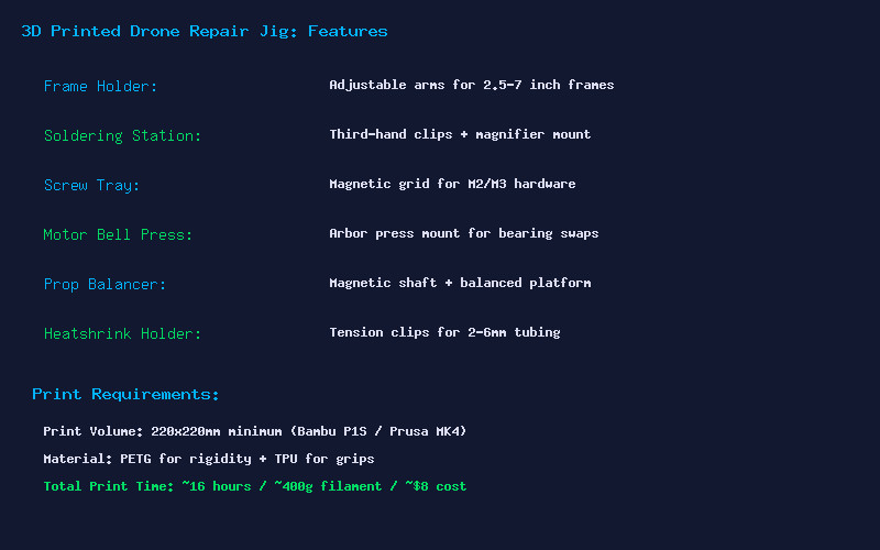
Frame Holder: The heart of the jig. Two adjustable arms with rubberized TPU grips clamp onto frame arms from 2.5-inch to 7-inch builds. Each arm slides along a dovetail rail and locks with a thumbscrew. The arms rotate 360 degrees so you can flip the quad for access to both top and bottom. Print the rails in PETG for rigidity and the grips in TPU for grip.
Soldering Station: Integrated third-hand clips on flexible arms position wires exactly where you need them. Add a mount for a magnifying glass or USB microscope. Include a brass sponge holder and a slot for your soldering iron when not in use. The clips should be spring-loaded and the arms should be stiff enough to hold position but easy to reposition one-handed.
Magnetic Screw Tray: A grid of hexagonal pockets with 6mm x 3mm neodymium magnets press-fit into the bottom. M2 and M3 screws snap into their own compartments and stay there even if you bump the workstation. The tray lifts out so you can carry hardware to your work area.
Motor Bell Press: A simple arbor press mount that uses an M8 threaded rod to apply controlled pressure for pressing motor bearings. Much safer than hammering them in with a socket, which can damage the bearing races.
Prop Balancer: Two precision-mounted bearings on an 8mm hardened steel rod. Place a prop on the shaft and the heavy side drops, telling you exactly where to sand or add tape. A balanced prop set reduces video jello and motor wear significantly.
Heatshrink Holder: A set of tension clips in diameters from 2mm to 6mm that hold heatshrink tubing while you position wires. No more chasing rolling tubing across the desk.
Printing and Assembly
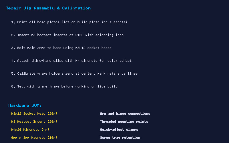
All structural parts should be printed in PETG at 245C nozzle, 80C bed, with 4 perimeters and 30% cubic infill. The base plate is the largest part – about 200x150mm – so make sure your build plate is clean and leveled. Print the base flat with no supports. The dovetail rails print on their sides for maximum strength along the sliding direction.
Install M3 heatset inserts at 210C using a soldering iron with a flat tip. Use M3x12 socket head screws for all structural connections and M4 wingnuts for quick-adjust clamps. The 6mm x 3mm magnets press-fit into the screw tray pockets – add a drop of CA glue if they are loose.
Hardware BOM
- M3x12 Socket Head Screws (x20) – Arm and hinge connections
- M3 Heatset Inserts (x20) – Threaded mounting points
- M4x20 Wingnuts (x4) – Quick-adjust clamps for frame holder
- 6mm x 3mm Neodymium Magnets (x10) – Screw tray retention
- 8mm Hardened Steel Rod (x2, 100mm long) – Prop balancer shaft
- M8x100 Threaded Rod – Motor bearing press
Total print time is approximately 16 hours across all parts, using around 400g of PETG. At $20 per kilogram, that is about $8 in filament. Add another $5-10 for the hardware kit, and you have a complete professional-grade repair workstation for under $20.
This is one of those projects that pays for itself the first time it saves you from losing an M2 screw or damaging a motor during a bearing swap. Print it, build it, and your repair workflow will never be the same.