
Racing drones are built for speed, but raw motor power only gets you so far. At 120 km/h and above, aerodynamic drag becomes the dominant force holding you back. A well-designed set of 3D printed fairings, canopies, and arm sleeves can cut drag by over 50%, adding 10-15% more top speed without changing a single electronic component. This guide covers the aerodynamics, design principles, and printing techniques to make your quad slice through air instead of fighting it.
The Physics of Drone Drag
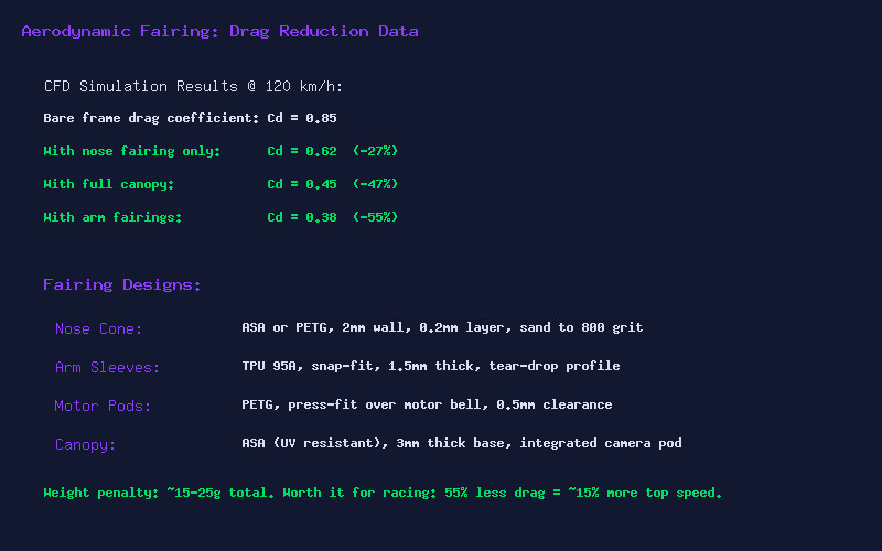
Drag force scales with the square of velocity. At 60 km/h, aerodynamic drag is noticeable. At 120 km/h, it is four times stronger. At 180 km/h, it is nine times stronger. Your bare carbon frame is essentially a blunt object with a drag coefficient (Cd) around 0.85 – comparable to a brick. Every sharp edge, exposed wire, and flat surface contributes to turbulent wake that costs you speed.
Computational fluid dynamics (CFD) simulations show that a full aerodynamic treatment – nose cone, arm sleeves, motor pods, and canopy – can reduce the effective Cd to around 0.38. That is a 55% reduction in drag force. At racing speeds, this translates directly to faster lap times and longer flight times at speed.
Fairing Components
Nose Cone: The most impactful single fairing. A teardrop-profile nose cone smooths airflow over the front of the frame, eliminating the blunt leading edge that creates the largest pressure drag. Design in ASA or PETG with a 2mm wall thickness. Sand to 800 grit and apply a clear coat for a glass-smooth finish. The nose cone should extend forward of the camera by 10-15mm to create a proper leading edge.
Arm Sleeves: Your frame arms are terrible aerodynamically – flat carbon plates perpendicular to airflow. TPU arm sleeves with a teardrop profile reduce arm drag dramatically. The sleeve should be 1.5mm thick, snap-fit over the arm, and extend from the frame body to just before the motor. Print in TPU 95A so they flex on impact instead of shattering.
Motor Pods: The spinning motor bell creates chaotic turbulence. A PETG motor pod that slips over the motor with 0.5mm clearance smooths the transition from arm to propeller. Be careful not to obstruct the motor cooling vents – add small NACA ducts if needed.
Full Canopy: A single-piece canopy that covers the entire frame from nose to tail, with integrated camera mounting and ventilation slots. This is the most aerodynamic option but also the heaviest. Reserve full canopies for dedicated racing builds where every tenth of a second counts.
Material Selection
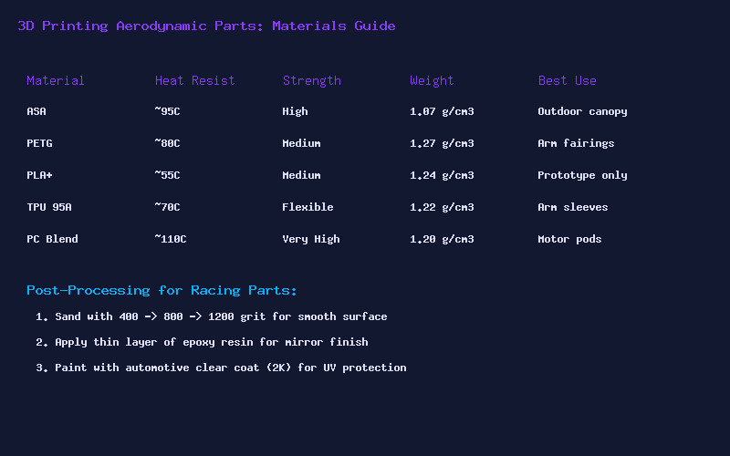
ASA is the premium choice for aerodynamic parts. It has higher temperature resistance (95C vs 80C for PETG), better UV stability, and sands to a smoother finish. The downside is that ASA requires an enclosure and proper ventilation due to styrene fumes. PETG is an excellent alternative that prints easily on most printers without an enclosure. PLA+ is acceptable for prototyping but will warp in the sun on a hot race day.
For arm sleeves that need to flex on impact, TPU 95A is the only logical choice. The flexibility absorbs crash energy and the sleeves will survive direct hits that would shatter rigid materials.
Post-Processing for Maximum Speed
3D printed surfaces are rough at the microscopic level. Layer lines create turbulence in the boundary layer. To achieve a truly slippery surface, wet sand the parts through a progression: 400 grit, then 800 grit, then 1200 grit. After sanding, apply a thin coat of epoxy resin (XTC-3D works well) and let it self-level. Finish with automotive 2K clear coat for UV protection and a mirror finish.
The total weight penalty for a full aero kit is 15-25 grams. On a 700g racing quad, that is less than 4% weight increase for a 55% drag reduction. The math is clear: aero is the best speed upgrade money cannot buy – you have to make it yourself.