
Introduction
Carbon fiber arms are the standard for FPV drones for good reason — they are light, stiff, and strong. But what if you break an arm on a Saturday morning and do not have a spare? Or what if you want to experiment with arm geometry that no manufacturer offers? 3D printing drone arms is surprisingly viable with the right materials, design principles, and print settings. This guide covers material selection, arm design strategies, print orientation, and real-world strength testing so you can print arms that survive actual flying.
Material Selection: What Actually Survives
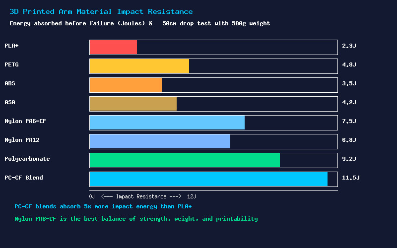
Not all filaments are created equal for structural drone parts. Here is how common 3D printing materials rank for arm durability, based on impact testing and real-world flight experience:
PLA+ — Acceptable for Testing Only
PLA+ is stiffer than standard PLA and slightly tougher, absorbing about 2.3J before failure in drop tests. It prints beautifully and costs little. However, PLA+ is brittle — it shatters rather than bends on impact. A PLA+ arm will survive gentle cruising but will snap immediately in a crash. Use PLA+ for prototyping arm geometry and fit-checking, then reprint in a tougher material for actual flight.
PETG — The Minimum Viable Material
PETG absorbs roughly double the impact energy of PLA+ (4.8J). It bends slightly before breaking, providing some warning before catastrophic failure. PETG arms can survive light crashes on 3-inch quads weighing under 250g. For anything larger or flown aggressively, PETG is marginal. Its layer adhesion, while better than PLA, is still the weak point in arm designs.
Nylon PA6-CF — The Sweet Spot
Carbon-fiber-filled nylon is the breakthrough material for printed drone arms. PA6-CF absorbs 7.5J of impact energy while offering excellent stiffness from the carbon fiber reinforcement. The nylon matrix provides toughness and layer adhesion, while the short carbon fibers increase rigidity and reduce warping during printing. At roughly $50-60 per kg, PA6-CF is expensive but produces arms that approach injection-molded nylon strength.
Critical requirements for PA6-CF: a hardened steel nozzle (0.4mm or 0.6mm), an enclosure maintaining 45-60C ambient temperature, and thorough filament drying (70C for 8+ hours before printing). PA6-CF absorbs moisture aggressively and prints terribly when wet.
Polycarbonate and PC-CF — Ultimate Strength
Pure polycarbonate (9.2J) and PC-CF blends (11.5J) offer the highest impact resistance of any printable material. The catch: PC requires 280-300C nozzle temperatures and 100-110C bed temperatures, which are beyond most consumer printers. PC-CF blends like Prusament PC Blend Carbon Fiber print at slightly lower temperatures (275C) but still demand an actively heated enclosure. If your printer can handle these temperatures, PC-CF produces arms stronger than some budget carbon fiber.
Arm Design: Geometry That Works
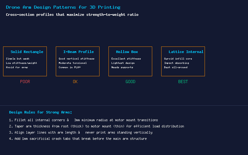
The cross-section of your arm determines its strength-to-weight ratio. Four patterns have proven effective:
Solid Rectangle — Avoid for Flight
A simple rectangular cross-section is the weakest design per gram. All material is at the neutral axis where it contributes minimally to bending stiffness. Use only for quick prototypes and fit tests.
I-Beam Profile — Good Vertical Stiffness
The I-beam concentrates material at the top and bottom flanges (far from the neutral axis) for maximum bending stiffness in the vertical direction — exactly where propeller thrust loads act. This is the best simple design for arms that do not need torsional stiffness. The web between flanges resists shear forces. Print I-beam arms flat on the bed for optimal layer orientation.
Hollow Box — Excellent All-Around
A hollow rectangular tube provides high stiffness in both vertical and torsional directions with minimal weight. The walls carry bending loads efficiently, and the closed cross-section resists twisting. This requires support material for the internal cavity roof, but the performance gain is worth the post-processing. Design with 2-3mm wall thickness and generous internal fillets at the corners.
Gyroid Lattice Internal — Best All-Around
Instead of a hollow cavity, fill the arm interior with 30-40% gyroid infill. The continuous curved surfaces of gyroid infill distribute impact forces omnidirectionally, absorbing energy through controlled compression of the infill structure. Combined with 4-6 solid perimeters for the outer shell, this design offers the best balance of strength, weight, and crash survivability. Gyroid-lattice arms often survive crashes that would snap hollow-box arms because the infill crushes progressively rather than failing catastrophically.
Critical Design Rules
- Fillet everything: The transition from the wide frame-mount root to the narrow motor-mount tip is a massive stress concentration. Use a minimum 5mm fillet radius at this transition. In CAD, this looks excessive — in reality, it is barely enough.
- Taper the thickness: The arm should be thickest at the frame attachment (highest bending moment) and taper to about 60% of that thickness at the motor mount. Linear taper is fine; parabolic taper is ideal.
- Sacrificial crash zones: Add a 1-1.5mm thin section deliberately designed to break. This absorbs crash energy and protects the frame body and motor from damage. The arm breaks — you print a new one in an hour for $0.50 instead of replacing a $15 motor.
- Motor mount reinforcement: The motor mounting holes concentrate stress. Add 2mm extra thickness locally around the motor bolt pattern, with generous fillets transitioning back to the arm cross-section.
Print Orientation: The Make-or-Break Setting
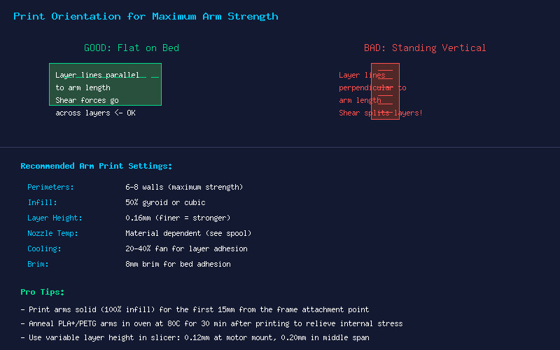
Print orientation is the single most important factor in arm strength. FDM prints are anisotropic — layer adhesion is always weaker than the material itself. An arm printed vertically will snap along layer lines like a stack of crackers. Always print arms flat on the bed, with the arm length parallel to the XY plane. This aligns layers perpendicular to the primary bending loads, where the material strength (not layer adhesion) carries the stress.
For arms longer than your build plate diagonal, split the design with a tongue-and-groove joint at a low-stress point mid-span. The joint should interlock mechanically and be secured with M2 bolts through printed bosses.
Print Settings Summary
- Perimeters: 6-8 walls (maximum strength). Walls contribute more to bending strength than infill.
- Infill: 50% gyroid or cubic. Higher infill increases weight faster than strength.
- Layer height: 0.16mm. Thinner layers improve layer adhesion and surface finish.
- Cooling: 20-40% part cooling fan. Too much cooling weakens layer adhesion.
- Brim: 8mm for bed adhesion on long thin parts.
- Solid infill: First 15mm from frame root should be 100% solid.
Conclusion
3D printed drone arms are not a permanent replacement for carbon fiber — but they are an excellent temporary fix, prototyping tool, and experimental platform. With Nylon PA6-CF or PC-CF filament, proper gyroid-lattice internal design, and flat print orientation, printed arms can survive dozens of flights on 3-5 inch builds. Print a set of emergency arms in PA6-CF, toss them in your field bag, and you will never lose a flying day to a broken carbon arm again.